Article Overview
The grounding wire in a secondary distribution box ensures safety and system stability, typically requiring copper conductors sized according to local standards and connected to a low-resistance earth path.
Wire Sizing and Material
For proper grounding, the wire size depends on the market and system requirements. In the US, a 10 AWG (5.26 mm²) copper wire is commonly used, while in other regions, a 6 mm² copper wire is standard . For connections between mounting plates and equipment like spindle plates, larger wires such as 16 mm² (or 6 AWG in the US) may be required to maintain low resistance and ensure safety under fault conditions . Copper is preferred for buried or exposed runs due to its high conductivity and corrosion resistance .
Connection Points
The grounding wire should be connected from a threaded stud at the bottom of the distribution box housing to the mounting plate, and then from the mounting plate to the central grounding point of the facility . This ensures that all metallic parts of the system are at the same potential, reducing the risk of electric shock and equipment damage.
Resistance Requirements
A properly installed grounding system should maintain a ground resistance of less than 0.1 ohm between all system parts . This low resistance ensures that fault currents are safely directed to the earth, protecting personnel and equipment . In some applications, additional grounding wires may be omitted if the cable lengths are short and multiple devices are grounded together, but the total resistance must still meet safety standards .
Safety and System Considerations
Grounding serves multiple purposes:
- Personnel Safety: Reduces the risk of electric shock by minimizing potential differences between conductive parts and the earth .
- Equipment Protection: Protects distribution equipment from lightning strikes, transient overvoltages, and fault currents .
- System Stability: Stabilizes voltage levels and ensures proper operation of protective devices like circuit breakers and relays .
- Fault Detection: Provides a clear path for fault currents, enabling rapid isolation of faults .
Installation Best Practices
- Use certified copper conductors and avoid aluminum for buried runs, as aluminum corrodes over time .
- Ensure mechanical protection for grounding conductors to prevent damage and maintain continuity .
- Test the grounding system after installation to verify resistance values and proper connections .
- Consider soil resistivity and environmental factors; in high-resistivity areas, deeper or chemically enhanced grounding electrodes may be necessary . By following these guidelines, the secondary distribution box will have a reliable grounding system that protects both personnel and equipment while maintaining system performance.
Grounding Requirements for Electrical Cables, Cable Trays, and
Guidelines for grounding electrical cables, busbars, and cable trays in wiring projects, ensuring safety and compliance
Ground Wire Size Chart NEC 2026: Complete Grounding Guide
NEC Table 250.122 is the primary reference for determining the minimum size of equipment grounding conductors
Grounding System Installation Standards for Distribution Boxes and
Whether you''re a seasoned pro or just starting out, this comprehensive guide will give you practical insights into proper
Information Bulletin 2025-003: Revised ES54 S0-04 Secondary
Temporary grounding 30° 30° Figure 1 – Temporary construction service Minimum 2''x4" bracing and stakes Customer-Owned
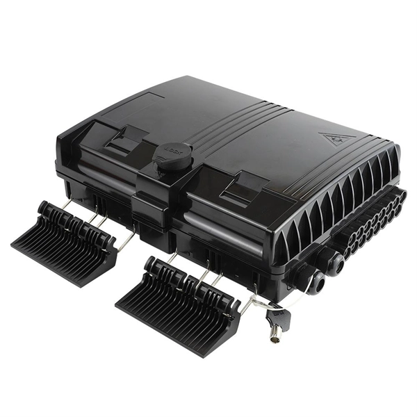
Standard grounding connection method for secondary distribution boxes
This Grounding Standard describes the technical requirements for grounding the SEC Distribution Network installations. SEC
Electrical grounding and bonding per NEC
Understanding correct grounding and bonding design and construction is crucial for proper electrical system operation
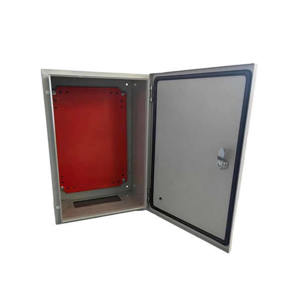
What are the regulations for the grounding wire of a secondary
Overview 26 mm 2 (10 AWG) ground wire must be used, and in all other markets a 6 mm 2 must be used. Secondary equipment
Correct Connection Method Of Grounding Wire Of
Following the above steps and precautions can ensure the correct connection of the
DISTRIBUTION BOX
Each DISTRIBUTION BOX and controller must be grounded. On the US market, a 5.26 mm 2 (10 AWG) ground wire
Microsoft Word
This Grounding Standard describes the technical requirements for grounding the SEC Distribution Network installations. SEC

Grounding Practices in Power Distribution Systems
The installation of grounding methods for transmission lines is absolutely necessary in order to guarantee the safety, dependability,
GROUND GRID SPECIFICATIONS
Each Power Circuit Breaker or Power Transformer having a bushing Voltage Transformer on the tank shall have the Voltage
Grounding in Power Transmission and Distribution Networks
Power transmission and distribution systems are earthed for electric shock and fault protection. This chapter presents the principles
Grounding Paper
Distribution System Grounding Fundamentals Edward S. Thomas, PE - Senior Member Richard A. Barber - Member Utility Electrical

How to Ground an Electrical Panel: NEC Requirements
This guide provides a comprehensive overview of the principles, components, and

UNDERGROUND ELECTRIC DISTRIBUTION CONSTRUCTION STANDARDS
SECONDARY SYSTEMS SECONDARY GROUNDING IDENTIFICATION Revised By: PARKTA LE OF CONTENT – SECTI N /
Distribution System Grounding
Most common problems are open secondary neutral, load incorrectly connected to the ground wire instead of neutral,
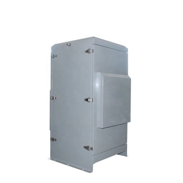
The installation requirements for the distribution box
Learn how to install a distribution box safely and correctly. Covers wiring, placement, standards, and expert tips for a
00 cover com_tech
5.38 Typical Distribution Transformer Core Form Design and Neutral Grounding Circuit Variation of Surge Impedance with Surge
Layout1
For grounding details see part-1 of grounding standard (typical arrangement of meter box as shown in Dwg.142 and Dwg.143 of
Ground Wire Sizing Guide | NEC Grounding Requirements
Size ground wires per NEC requirements. Learn equipment grounding conductor sizes, grounding electrode
Design Standard Grounding and Bonding for Electrical Systems
Design and specify the installation of equipment grounding such that metallic structures, enclosures, raceways, junction boxes, outlet
GROUND GRID SPECIFICATIONS
PURPOSE AND SCOPE IPMENT, STRUCTURES, ETC. IN ELECTRICAL STATIONS INCLUDING TRANSMISSION AND
The Basics of Grounding and Bonding
Article 250 of the NEC covers the grounding and bonding of electrical systems. By definition, as well as by function, grounding and
IEEE Guide for the Design and Installation of Cable Systems in
Abstract:The design, installation, and protection of wire and cable systems in substations are covered in this guide, with the objective

Distribution System Grounding
Four‐wire systems are superior to three‐wire systems for serving single‐phase loads and are predominant in North America. In
SDCS-03 DISTRIBUTION NETWORK GROUNDING
Every pole with MV equipment installation shall be grounded with minimum of 4 ground rods. In high soil resistivity areas, such as
Low-voltage distribution networks
The distribution is effectively carried out at medium voltage in a way, which again differs from standard European
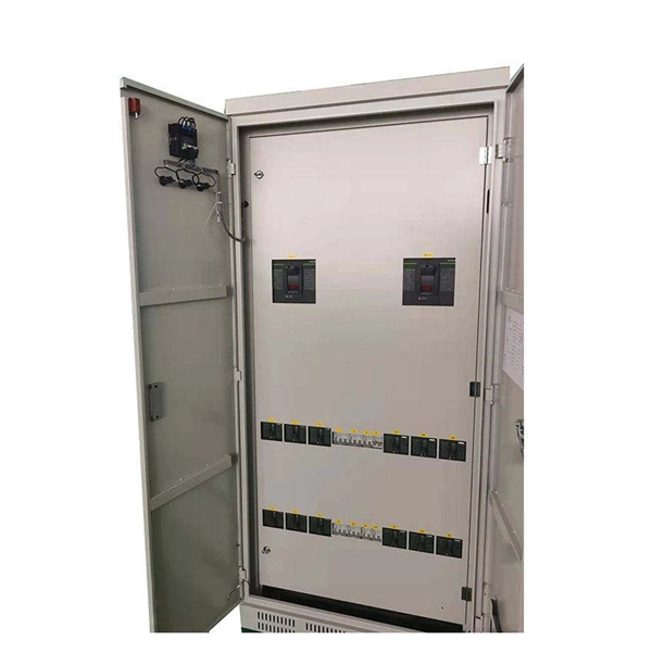
Distribution System Neutral Grounding Methods and Transformer
This report is intended to be a primer that illustrates the fundamentals of neutral grounding and transformer winding configuration as
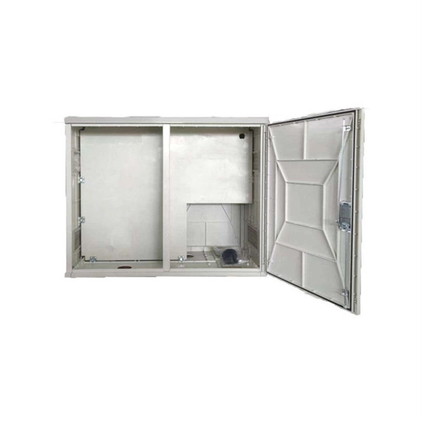
Related Resources
- Multimode cable pigtails and patch cords
- Peru door-to-door shipping of 25G carrier-grade routers
- How to connect a temperature-sensing fiber optic cable to a sensor
- What does multimode optical cable represent
- How to whiten ceramic inserts
- South Sudan makes electrical distribution boxes
- Belgian Data Center EMS380V
- Installation of fiber optic cable for pipeline temperature measurement in Bolivia
- Angola Customs Costs ONT Optical Network Terminal 800G
- Core Components of an Optical Circulator
- Where are the manufacturers of optical cable headers in Suriname
- Fibre Channel 1553 Reliability